
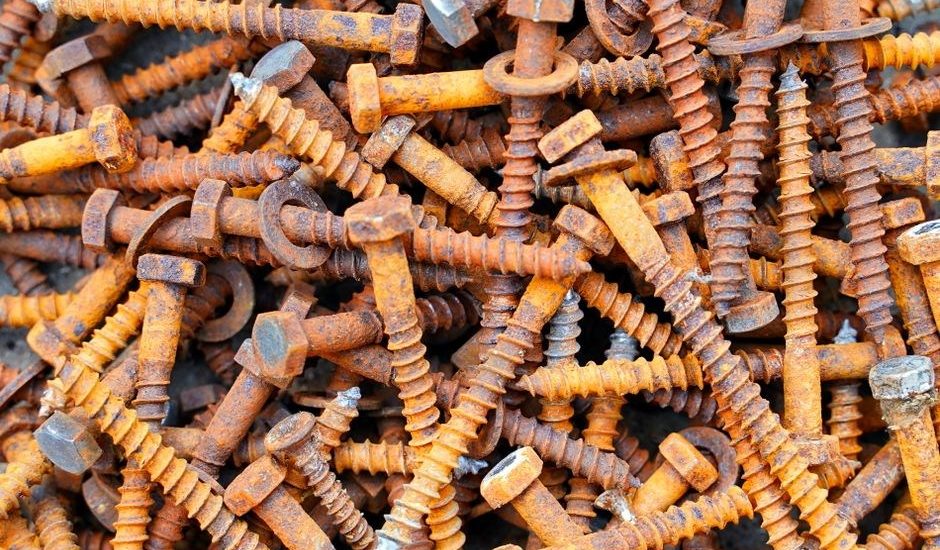
Machine Screw Size Fundamentals
Machine screws provide a standardized, reliable fastening solution for mechanical assemblies. Their uniform diameters and thread pitches allow quick part identification, streamlined inventory, and precise torque control. Mastering the sizing system simplifies design, procurement, and maintenance. Ideal for all use!!.
Definition and Core Parameters
Machine screws are precision‑cut fasteners that rely on a consistent major diameter, thread pitch, and head form to guarantee a secure fit across a wide range of materials. The core parameters that define a screw’s identity are: the nominal diameter, the pitch or thread density, the length, the head type, and the drive style. In the metric system, the diameter is expressed in millimetres (e.g., M3, M4, M5), and the pitch is the distance between adjacent threads in millimetres (e.g., 0.5 mm for M3). In the imperial system, the diameter is given in inches and the pitch is expressed as threads per inch or as a fractional pitch (e.g., 1/4‑20, 1/4‑28). The length is measured from the base of the head to the tip, excluding the head for countersunk or pan heads and including it for flat or button heads. The head shape—flat, pan, button, or hex—determines the bearing surface and torque application, while the drive—slotted, Phillips, hex, or Torx—dictates the tool interface. Together, these parameters enable engineers to select a screw that matches the mechanical load, material thickness, and assembly constraints. Accurate identification of each parameter ensures compatibility with standard thread libraries, reduces the risk of cross‑threading, and supports consistent manufacturing tolerances across the supply chain. By mastering these fundamentals, designers and technicians can streamline part selection, simplify procurement, and achieve reliable, repeatable fastening performance in every application. These standards also dictate recommended torque values and material grades for optimal durability.
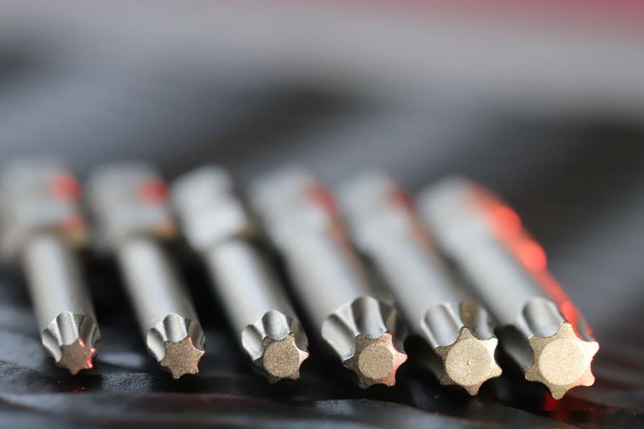
Threading Basics: Pitch vs. Revolutions Per Inch
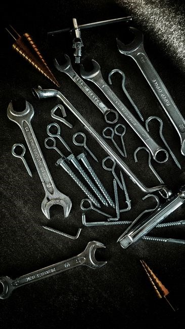
In threaded fasteners, the pitch defines the axial distance between two consecutive thread peaks, measured in millimetres for metric screws or in inches for imperial screws. A finer pitch means more threads per unit length, which increases the surface area for load distribution and allows tighter torque control. In the imperial system, thread density is commonly expressed as threads per inch (TPI). For example, a 1/4‑20 screw has 20 threads per inch, while a 1/4‑28 screw has 28 threads per inch, indicating a finer pitch. The relationship between pitch and TPI is reciprocal: a pitch of 1.27 mm corresponds to 20 TPI, whereas a pitch of 0.9 mm corresponds to 28 TPI. Engineers select pitch or TPI based on required strength, material, and manufacturing capabilities. Finer threads provide higher shear strength and better resistance to loosening, but they also increase manufacturing time and cost. Coarser threads are faster to produce and can accommodate larger loads per thread, but they may be more prone to stripping under high torque. The choice between pitch and TPI also affects the screw’s tolerance class and the required torque settings. Standardised thread series such as UNC, UNF, and metric M ensure compatibility across suppliers and reduce the risk of cross‑threading. Understanding the pitch/TPI relationship is essential for accurate part selection, torque calculation, and ensuring long‑term reliability in mechanical assemblies. This overview equips designers with threading fundamentals now.
Length Measurement Conventions
When a machine screw is specified, the overall length is measured from the very tip of the threaded portion to the top of the head. For flat‑head or pan‑head screws, the head height is included in this measurement; for countersunk or socket‑head screws, the length is measured from the base of the head to the tip, excluding the head. In metric practice, lengths are expressed in millimetres (mm) and typically rounded to the nearest 0.5 mm. In the imperial system, lengths are given in inches, often using fractional notation such as 1‑1/2″, 5‑3/8″, or 1‑3/4″. The threaded portion, or pitch length, is the distance from the start of the thread to the tip and is usually shorter than the overall length because the head occupies a portion of the screw’s length. Standardised length series exist for both metric and imperial screws; for example, the M6 series includes 10 mm, 12 mm, 15 mm, and 20 mm lengths, while the 1/4‑20 series offers 1‑1/2″, 5‑1/4″, 3‑1/2″, and 1‑3/4″ lengths. Accurate length selection is critical for ensuring proper engagement of the screw threads within a mating bore, preventing over‑penetration or insufficient grip. When designing assemblies, it is common practice to select a screw length that provides at least 1.5 times the thickness of the material being fastened, while also allowing for a 10–15 % safety margin to accommodate manufacturing tolerances. Proper documentation of length conventions in engineering drawings and part lists eliminates confusion during procurement and assembly, thereby enhancing product reliability and reducing costly rework.
Metric Machine Screw Standards
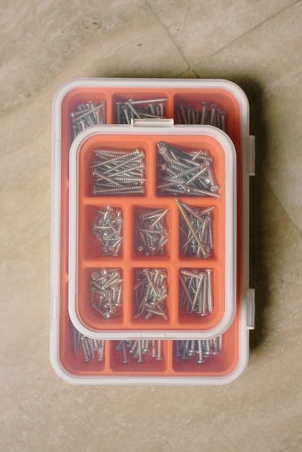
Metric machine screws follow ISO 261, 261A, and 261B. Diameters range M1–M100 with coarse pitches (1.0–1.75 mm) and fine pitches (0.5–0.75 mm). Common sizes include M3, M4, M5, M6, M8, M10, M12, M16, M20, M25, M30, used in automotive, aerospace, electronics industrial parts.
Standard Metric Thread Pitch Intervals
Metric thread pitch intervals are defined by ISO standards and are critical for ensuring compatibility across international manufacturing. The coarse pitch series, designated as ‘P’ or ‘CP’, typically ranges from 0;5 mm to 1.75 mm for diameters between M1 and M100. Fine pitch series, labeled ‘F’ or ‘FP’, offers tighter threads with pitches as small as 0.25 mm for M1 and up to 0.75 mm for larger diameters. The pitch is calculated as the distance between adjacent thread peaks measured along the thread axis. For example, an M6 × 1.0 screw has a 1.0 mm pitch, meaning each thread turns 1.0 mm along the shaft. In contrast, an M6 × 0.75 screw has a finer pitch, allowing greater thread engagement and load distribution.
Standard pitch tables list each diameter with its corresponding coarse and fine pitches, enabling designers to select the appropriate thread for strength, speed of assembly, and material compatibility. When converting between metric and imperial systems, remember that 1 mm ≈ 0.03937 inches; thus a 1.0 mm pitch approximates 25.4 TPI. Precision machining and quality control are essential, as deviations beyond ±0.05 mm can compromise thread fit and lead to loosening or failure. Engineers often choose coarse pitches for high‑speed applications and fine pitches for precision assemblies requiring tighter tolerances. Adhering to these intervals ensures reliable performance in automotive, aerospace, electronics, and general mechanical engineering. Typical thread depth equals 1.25 times pitch, ensuring sufficient shear area for high‑load joints!
Common Metric Sizes and Their Typical Applications
Common metric machine screws span a wide range, from the ultra‑small M1.6 to the robust M30. Designers select a size based on required load, material thickness, and assembly speed. M1.6 and M2 are favored in precision electronics and watchmaking, securing delicate components. M2.5 and M3 are ubiquitous in circuit boards, small housings, and portable devices. M3.5 and M4 are standard in automotive trim, power tools, and light machinery, offering a balance between strength and compactness. M5 and M6 are used in automotive interior panels, industrial fixtures, and medium‑strength assemblies. M8 screws are common in engine components, structural brackets, and heavy‑duty machinery. M10 and M12 are often employed in heavy equipment, industrial frames, and large structural assemblies. M14 and M16 appear in construction fasteners, heavy machinery, and large automotive assemblies. M18, M20, and M22 are typical for large structural steelwork, machine frames, and aerospace applications. M24, M28, and M30 are reserved for high‑load structural steelwork, large machinery frames, and aerospace structural joints where maximum load capacity and durability are essential. When selecting a metric screw, thread pitch matters: coarse pitches (e.g., 1.0 mm for M6) give assembly, while fine pitches (e.g., 0.75 mm for M6) provide tolerances and load capacity. Material choices—steel, stainless steel, aluminum, or brass—affect performance in corrosive, high‑temperature, or lightweight environments. Standardization across ISO 261 and ISO 965 ensures interchangeability worldwide, simplifying supply chains and reducing inventory costs. and promotes compliance now
Imperial Machine Screw Standards
Imperial machine screws follow the ANSI/ASME standards, using inch diameters and TPI. UNC (coarse) threads have 20–32 TPI, while UNF (fine) threads range 40–80 TPI. These series ensure uniformity in automotive, aerospace, and construction fasteners worldwide. They ensure joint strength and reliable torque.!!!!
UNC vs. UNF Thread Series Explained
UNC (Unified National Coarse) and UNF (Unified National Fine) are the two primary thread families used in the United States for machine screws. The key difference lies in the pitch: UNC threads have a coarser pitch (fewer threads per inch), typically ranging from 20 to 32 threads per inch (TPI), whereas UNF threads are finer, with pitches from 40 to 80 TPI. This finer pitch allows UNF screws to achieve higher torque and tighter tolerances, making them suitable for precision assemblies, aerospace, and automotive applications where vibration resistance is critical. UNC screws, on the other hand, provide greater load‑bearing capacity and are often chosen for structural or heavy‑load connections, such as in machinery, construction, and general mechanical work. Both series share the same major diameter designation, but the thread depth and number of threads per inch differ, which affects the shear area and thread engagement. When selecting between UNC and UNF, engineers must consider factors such as required torque, material strength, vibration environment, and the need for fine adjustment. For example, a 1/4‑20 UNC screw is common in structural brackets, while a 1/4‑32 UNF screw is preferred in high‑precision gear assemblies; Proper selection ensures optimal performance, longevity, and safety of the assembled components.
Choosing the correct thread family involves considering material friction and galling. Manufacturers provide torque charts to prevent stripping or loosening. Following these guidelines ensures reliability for safety for safety
Standard Imperial Thread Sizes and Pitch Notation
In the United States, machine screw sizes are expressed as a fraction of an inch for the nominal diameter followed by a dash and the number of threads per inch (TPI). The most common series are UNC (Unified National Coarse) and UNF (Unified National Fine). For example, a 1/4‑20 screw has a 0.250‑inch major diameter and 20 threads per inch, while a 1/4‑32 screw has the same diameter but 32 threads per inch. The pitch, defined as the distance between adjacent threads, is the reciprocal of the TPI; thus a 1/4‑20 screw has a pitch of 0.050 inches (1/20), whereas a 1/4‑32 screw has a pitch of 0.03125 inches (1/32). Standard sizes range from 1/16 to 1/4 for small bolts, 5/16 to 3/8 for medium bolts, and 1/2 to 1 inch for larger bolts, with each size having both coarse and fine variants. The notation “1/4‑20” or “1/2‑13” is universally understood by machinists, suppliers, and manufacturers, enabling quick identification of the required thread type. The Unified Thread Standard (UTS) provides a table of all standard sizes, including the pitch, pitch diameter, and thread depth for each combination. Engineers often refer to UTS charts or use online conversion tools to match metric and imperial sizes. Proper selection of thread pitch not only affects the mechanical strength and load capacity but also influences the ease of assembly, the likelihood of galling, and the ability to achieve a secure lock‑in under vibration. Therefore, understanding the standard imperial thread sizes and pitch notation is crucial for accurate design, procurement, and quality control in any mechanical or structural application.
Selecting and Using Machine Screws
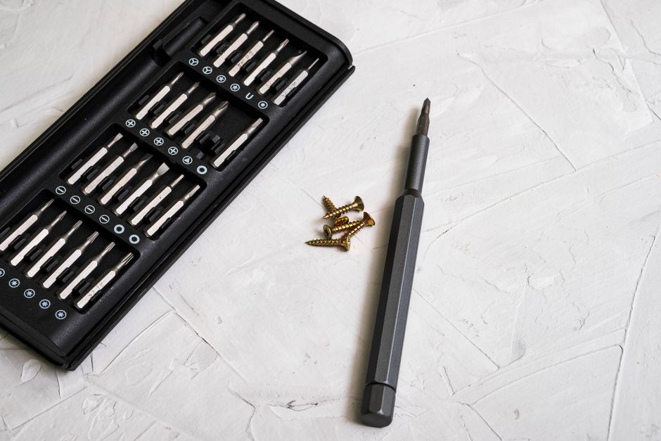
Choosingtherightmachinescrewhingesonload,material,andenvironment.Startbydeterminingtherequired torqueandthreadengagementdepth.Selectascrewwithathreadpitchthatbalancesstrengthandassemblyspeed.Useproperdrivestypes—slotted,Phillips,orhex—toensureveryaccuratetighteningandavoid tightfirmsecurely stripping
Choosing the Correct Screw for Load and Material
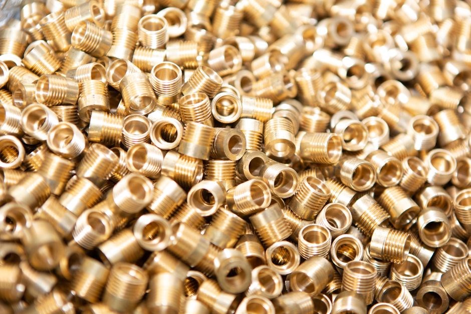
Choosing the right machine screw starts with the load type—tension, shear, or both. Determine the maximum axial force the screw must carry; For pure tension, the screw’s tensile strength, derived from its diameter and material grade, must exceed the load with a safety factor of 2–3. In shear, use the screw’s shear strength, roughly 0.5–0.6 of its tensile value.
Material selection follows the load analysis. High‑strength steels such as A2 or A4 offer superior tensile and shear capacities, while stainless steels (304, 316) provide corrosion resistance for aggressive environments. For aluminum or composite parts, consider using a screw with a hardened steel core or a titanium alloy to avoid galling and to match the modulus of elasticity, which reduces stress concentrations
Thread pitch and diameter directly affect load distribution. A coarse pitch (e.g., 1.5 mm for M10) provides engagement and higher load capacity for softer materials, whereas a fine pitch (e.g., 0.8 mm for M10) offers better torque control precision. The screw’s thread depth determines bearing area; deeper threads increase load capacity but may reduce overall strength if the core diameter is too small now.soon
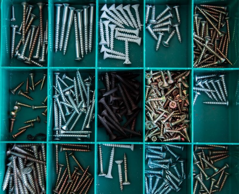
Finally, consider the installation method. For high‑speed or automated assembly, use screws with a drive type that minimizes cross‑driving and ensures consistent torque. Apply a suitable lubricant or thread‑locking compound to prevent loosening under vibration. Verify that the screw’s length exceeds the required engagement length—typically 1.5 to 2 times the pitch for full thread engagement—to guarantee a secure joint again soon
Common Pitfalls and Best Practices for Installation
When installing machine screws, avoid common pitfalls that compromise joint integrity. Selecting a screw with insufficient thread depth or diameter for the load leads to premature failure. Over‑tightening can strip threads or crack the material. Use a calibrated torque wrench and follow manufacturer torque tables. Neglecting to pre‑drill holes causes cross‑driving or misalignment; always drill to the correct pilot size. Ignoring lubrication increases friction and leads to galling, especially with stainless or titanium screws. Apply thread‑locking compound or a light oil to reduce wear. Installing the screw in a material that is too soft for the chosen thread pitch can cause thread stripping; match the pitch to the material hardness. Omit a backing plate or washer when the load is high and the load shifts to the screw head, causing head damage. Use washers or backing plates to distribute load evenly. By avoiding these pitfalls and following best practices—proper sizing, correct torque, proper drilling, lubrication, and load distribution—installations will be reliable, durable, and safe.
Verify the screw’s material grade matches the operating temperature; low‑grade steel at high temperatures may soften. Inspect threads for burrs before assembly. Use a self‑tap drill bit for composites. Perform a pull test after installation to confirm joint integrity. Document torque settings. Remember to keep the screw head aligned with the mating surface to avoid uneven load distribution. If vibration is present, use a lock‑nut or nylon insert to prevent loosening. Follow torque tables precisely.